
 EN
EN ES
ES ITA
ITA DE
DE FR
FRWhy Does an FBG Sensor Still Drift After Temperature Compensation?

Why Does an FBG Sensor Still Drift After Temperature Compensation?
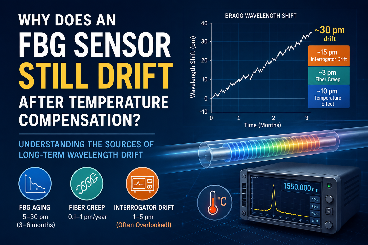
Understanding the Sources of Long-Term FBG Wavelength Drift
Fiber Bragg Grating (FBG) sensors are widely used for strain, temperature, pressure, vibration, and structural health monitoring. Their high sensitivity and immunity to electromagnetic interference make them attractive for long-term measurements in demanding environments.
However, engineers sometimes encounter an unexpected problem: an FBG sensor can still show significant wavelength drift even after temperature compensation has been applied.
For example, an FBG sensor may be calibrated initially and then show a wavelength shift of around 30 pm several months later. If temperature compensation has already been implemented, where does the remaining drift come from?
The answer is that long-term FBG drift is usually not caused by a single factor. It can result from the combined effects of FBG aging, fiber creep, and drift within the optical interrogation system. Temperature compensation addresses only part of the problem.
1. Why Does the Bragg Wavelength Drift?
The Bragg wavelength of an FBG is determined primarily by the grating period and the effective refractive index of the fiber:
λB = 2neffΛ
where:
λB is the Bragg wavelength
neff is the effective refractive index
Λ is the grating period
Any factor that changes the effective refractive index or grating period can therefore cause the Bragg wavelength to shift. Temperature and mechanical strain are two of the most important factors.
The wavelength response can be approximately expressed as:
Δλ / λ = (1 − pe)ε + (α + ξ)ΔT
where:
pe is the effective photoelastic coefficient
ε is strain
α represents the thermal expansion coefficient
ξ represents the thermo-optic coefficient
ΔT is the temperature change
For a typical FBG operating around 1550 nm, a temperature change of 1°C can result in a wavelength shift of approximately 10–13 pm. This temperature sensitivity is fundamental to FBG sensing, but it is also one of the major contributors to wavelength variation in practical measurements.
2. Three Major Sources of Long-Term FBG Drift
When an FBG sensor is used over months or years, its measured wavelength can be affected by several mechanisms.
| Source | Typical Drift Level* | Possible Mitigation |
|---|---|---|
| FBG stress relaxation / aging | 5–30 pm over 3–6 months | Pre-aging / thermal annealing |
| Fiber creep | 0.1–1 pm/year | Metal-coated fiber, such as aluminum or gold coating |
| Interrogator light-source drift | 1–5 pm | Periodic wavelength calibration |
*The values above are the typical figures presented in the source material and should be regarded as engineering reference values rather than universal specifications.
Let's look at each source in more detail.
2.1 FBG Stress Relaxation and Aging
One potential source of long-term wavelength drift is stress relaxation within the FBG structure.
After fabrication and installation, the grating and surrounding fiber can undergo gradual mechanical relaxation. This process can cause the measured Bragg wavelength to change over time, even when the external environmental conditions appear to remain stable.
The source material estimates a drift of approximately 5–30 pm over 3–6 months and identifies pre-aging or thermal annealing as a possible mitigation method.
For applications requiring long-term stability, it is therefore important to consider not only the initial calibration accuracy of an FBG sensor, but also how the sensor behaves after extended operation.
2.2 Fiber Creep
Another source of long-term drift is fiber creep.
When an FBG sensor is permanently attached to a structure, the mechanical state of the fiber can gradually change. Over long periods, this can introduce a small but measurable change in the Bragg wavelength.
The source material cites a typical fiber-creep contribution of approximately 0.1–1 pm/year and suggests metal-coated fibers, such as aluminum- or gold-coated fibers, as one possible approach for reducing this effect.
Although the drift associated with fiber creep may be relatively small compared with some other mechanisms, it can become important in applications requiring very high long-term measurement stability.
3. The Often-Overlooked Factor: Interrogator Drift
One of the less obvious sources of wavelength drift is the FBG interrogator itself.
Many engineers naturally focus on the stability of the FBG sensor and the temperature compensation algorithm. However, the optical interrogation system is also part of the measurement chain.
An FBG interrogator typically uses an optical source, such as a superluminescent diode (SLED) or other broadband optical source. Changes in the operating temperature and characteristics of the optical source can influence the wavelength measurement.
As a result, even if the FBG sensor itself remains stable, the measured wavelength can still shift because of changes within the interrogation system.
This is why periodic wavelength calibration of the interrogator can be an important part of maintaining long-term measurement accuracy.
The source material identifies interrogator or light-source drift as a particularly easy factor to overlook and gives a typical reference level of approximately 1–5 pm.
4. Why Does Temperature Compensation Not Eliminate the Drift?
If temperature is one of the main causes of FBG wavelength variation, it seems reasonable to assume that temperature compensation should solve the problem.
In practice, however, temperature compensation has an important prerequisite:
The FBG sensor and the reference temperature sensor must experience essentially the same temperature conditions.
In real-world installations, this condition is not always satisfied.
Thermal Lag
A reference FBG may be mounted on the surface of a structure while the measurement FBG is embedded inside it.
The two sensors may therefore respond to temperature changes at different rates.
During a rapid temperature change, the reference sensor may indicate that the temperature has already changed while the measurement FBG is still responding to the previous thermal condition. This difference can introduce a temporary compensation error.
Dynamic Temperature Gradients
Temperature compensation is often much more straightforward under relatively stable thermal conditions.
In a dynamic environment, however, temperature gradients can develop within the structure. Different FBGs may experience different temperatures or respond to those temperature changes at different rates.
As a result, a compensation model that performs well under static conditions may not completely eliminate wavelength errors during rapid thermal changes.
Strain–Temperature Coupling
FBG sensors are sensitive to both strain and temperature.
Changes in the mechanical state of the sensor can therefore affect the measured wavelength, while environmental and structural changes may occur simultaneously.
This coupling creates additional challenges when attempting to separate the true strain signal from temperature-related wavelength variations.
5. A 30 pm Drift Does Not Necessarily Have a Single Cause
Suppose an FBG sensor was calibrated initially and, three months later, its measured wavelength has shifted by approximately 30 pm.
It may be tempting to attribute the entire change to temperature.
However, long-term wavelength drift is better understood as the combined result of multiple mechanisms:
FBG aging + fiber creep + interrogation-system drift + environmental effects
The source material provides an illustrative breakdown of a 30 pm drift:
Temperature-related contribution: approximately 10 pm
Fiber creep: approximately 3 pm over three months
Interrogation-system drift: approximately 15 pm
The remaining difference can come from the combined effects of the sensor, installation, environmental conditions, and measurement system. These figures should be treated as an illustrative engineering analysis rather than a universal breakdown applicable to every FBG system.
This is an important point for long-term FBG measurements:
A measured wavelength shift should not automatically be interpreted as sensor drift.
The entire measurement chain needs to be considered.
6. How Can Long-Term FBG Stability Be Improved?
For applications where long-term wavelength stability is important, several measures can be considered.
1. Pre-age the FBG sensors
Thermal annealing or other pre-aging processes can help reduce subsequent stress relaxation and improve long-term stability.
2. Select an appropriate fiber coating
For applications sensitive to long-term mechanical creep, the fiber coating and packaging structure should be considered during sensor selection.
Metal-coated fibers, including aluminum- or gold-coated fibers, may be considered for certain demanding applications.
3. Improve temperature compensation
The reference temperature sensor should be positioned so that it experiences thermal conditions as close as possible to those of the sensing FBG.
For dynamic applications, the thermal response time and installation configuration of both sensors should also be considered.
4. Calibrate the interrogator periodically
Temperature compensation cannot compensate for every source of measurement-system drift.
Periodic calibration of the interrogator can help identify changes originating from the optical measurement system itself. The source material specifically suggests periodic wavelength calibration, with a calibration interval of approximately three months using a reference standard.
5. Evaluate the complete measurement chain
For high-precision applications, the sensor should not be evaluated independently from the interrogator.
A more complete stability assessment should consider:
FBG → fiber → installation/packaging → temperature environment → optical interrogator → calibration reference → data-processing algorithm
This approach makes it easier to identify where long-term measurement errors are actually coming from.
7. Conclusion
Long-term FBG wavelength drift is a multi-factor problem.
Temperature is certainly an important source of wavelength variation, but temperature compensation alone does not necessarily eliminate long-term drift. FBG aging, fiber creep, thermal gradients, strain–temperature coupling, and optical interrogation-system stability can all contribute to the final measurement result.
When an FBG sensor shows a wavelength shift after several months of operation, the first question should therefore not simply be:
“Has temperature compensation been applied?”
Instead, a better question is:
“Which part of the entire measurement chain is contributing to the observed drift?”
For long-term and high-precision FBG sensing applications, sensor pre-aging, appropriate packaging, carefully designed temperature compensation, and periodic interrogator calibration should all be considered as part of the measurement strategy.
Ultimately, achieving stable FBG measurements is not just about selecting a high-quality sensor. The stability of the entire sensing and interrogation system matters.