
 EN
EN ES
ES ITA
ITA DE
DE FR
FRAPD Gain Set to 100: Noise Amplified 30×, Signal Only 10×

APD Gain Set to 100: Noise Amplified 30×, Signal Only 10×
Are You Amplifying the Signal—or Amplifying the Noise?
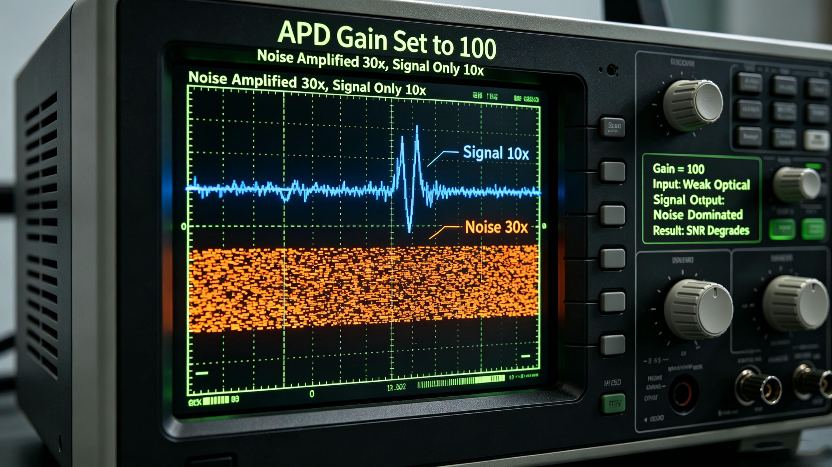
Increasing the gain of an avalanche photodiode (APD) from 10 to 100 does indeed increase the signal by approximately 10×. However, under typical conditions, the noise can increase by roughly 30×.
In a typical calculation based on the McIntyre model, increasing the APD gain to its maximum can cause the SNR to decrease from approximately 18 dB to 8 dB.
So, are you actually amplifying the signal—or are you amplifying the noise?
The key concept is the excess noise factor of an APD. It can be approximately described as:
F(M) ∝ Mˣ
where M is the avalanche gain and x is the excess-noise exponent. For typical InGaAs APDs, x is approximately 0.7–1.0.
This means that as the gain increases, every additional increment of gain can introduce a disproportionately larger amount of noise. As a result, there is an optimal gain, Mopt, and this optimum is often much lower than the maximum available gain.
1. APD Gain Is Not "Free"
An APD achieves internal optical gain through impact ionization.
In simplified terms, an APD with a multiplication factor M produces an average of M carriers from one photogenerated carrier. At first glance, this seems to suggest that both the signal and noise should simply be multiplied by M, leaving the SNR unchanged.
In reality, however, the avalanche multiplication process is statistical.
Different carriers have different probabilities of triggering additional ionization events. This randomness produces fluctuations in the avalanche gain, resulting in additional noise.
This phenomenon is described by the excess noise factor, F(M):
F(M) = kM + (1 − k)(2 − 1/M)
where:
k is the ionization coefficient ratio, defined as the electron ionization rate divided by the hole ionization rate
M is the APD multiplication gain
In the limiting cases:
When k → 0, corresponding approximately to single-carrier avalanche multiplication, F(M) → 2 − 1/M
When k → 1, corresponding to multiplication involving both carriers, F(M) → M
For simplified engineering analysis, an empirical form commonly used with the McIntyre model is:
F(M) = Mˣ
where x is the excess-noise exponent. The original source gives typical values of approximately:
Si APD: x ≈ 0.3–0.5
InGaAs APD: x ≈ 0.7–1.0
The difference is significant.
For example, when M = 100:
For a Si APD with x = 0.4:
F ≈ 100⁰·⁴ ≈ 6.3
For an InGaAs APD with x = 0.85:
F ≈ 100⁰·⁸⁵ ≈ 50.1
Thus, under this simplified model, the same nominal gain of 100 can result in dramatically different excess-noise behavior depending on the APD material and multiplication characteristics.
2. SNR vs. Gain: It Rises First, Then Falls
The total noise in an APD receiver typically includes:
Shot noise associated with the photocurrent and dark current
Thermal noise associated with the transimpedance amplifier and load
The source gives the following expression for the receiver SNR:
SNR = (Iph · M)² / [2q(Iph + Id)F(M)M²B + 4kTB/RL]
where:
Iph is the photocurrent
Id is the dark current
B is the bandwidth
RL is the load resistance
q is the elementary charge
k is the Boltzmann constant
T is the absolute temperature
The important point is that the effect of increasing gain depends on which noise source dominates.
When thermal noise dominates
When:
4kTB/RL >> shot-noise term
increasing the APD gain can amplify the signal sufficiently to overcome the receiver's thermal noise.
In this operating region, increasing M can improve the SNR. This is where APD gain provides a clear benefit.
When shot noise dominates
As the APD gain becomes higher, the system can enter a regime where shot noise becomes dominant.
The numerator of the SNR expression increases approximately as:
M²
while the noise contribution associated with avalanche multiplication increases approximately as:
F(M) · M² ∝ M²⁺ˣ
Because the denominator grows faster than the numerator, the SNR eventually begins to decrease.
This is the physical reason why higher APD gain does not necessarily produce better SNR.
3. An Example: InGaAs APD with x = 0.85
Consider an InGaAs APD with:
x = 0.85
The source provides the following simplified comparison:
Gain M | F(M) = Mˣ | Signal Power ∝ M² | Noise Power ∝ F·M² |
1 | 1 | 1 | 1 |
10 | 7.1 | 100 | 710 |
20 | 12.6 | 400 | 5,040 |
50 | 28.5 | 2,500 | 71,250 |
100 | 50.1 | 10,000 | 501,000 |
The important trend is clear.
From M = 10 to M = 100:
Signal power increases by 100×
Noise power increases by approximately 705×
Therefore, increasing the gain by another factor of 10 does not provide a corresponding improvement in SNR. Instead, the SNR deteriorates significantly.
The practical lesson is simple:
The maximum APD gain is not necessarily the optimum APD gain.
4. Deriving the Optimal Gain Mopt
The optimal APD gain can be obtained by differentiating the SNR with respect to the multiplication gain and setting the derivative to zero:
d(SNR)/dM = 0
The source gives the following approximate expression:
Mopt ≈ [4kTB / (x · q · Iph · RL)]1/(2+x)
where:
x is the excess-noise exponent
Iph is the photocurrent
This equation reveals two important relationships:
Higher photocurrent → lower optimal gain
Higher excess-noise exponent x → lower optimal gain
In other words, the optimum gain depends not only on the APD itself, but also on the optical power and receiver operating conditions.
Example: InGaAs APD
For an InGaAs APD with:
x = 0.85
Received optical power ≈ −20 dBm
Iph ≈ 10 μA
Bandwidth = 1 GHz
RL = 50 Ω
the source estimates:
Mopt ≈ 15–25
For a Si APD under the same assumed conditions:
Mopt ≈ 50–100
This helps explain why Si APDs can often operate at significantly higher multiplication gains than InGaAs APDs under comparable conditions.
Importantly, Mopt is not a fixed value.
As the received optical power increases, the optimal gain decreases.
This is somewhat counterintuitive: stronger optical signals can require lower APD gain.
5. Why Is InGaAs APD Noise Higher Than Si APD Noise?
The fundamental reason is related to the ionization coefficient ratio, k.
The source compares several APD materials as follows:
Material | Typical Wavelength Range | k = α/β | x | Typical Mopt Range |
Si | 400–1000 nm | 0.02–0.05 | 0.3–0.5 | 50–200 |
Ge | 1000–1600 nm | 0.5–0.8 | 0.8–1.0 | 5–10 |
InGaAs | 1000–1700 nm | 0.3–0.5 | 0.7–1.0 | 10–30 |
InAlAs (SAM) | 1000–1700 nm | 0.1–0.3 | 0.5–0.7 | 20–50 |
According to the source, Si has a very low k value, approximately 0.02–0.05. This means that avalanche multiplication is largely dominated by one carrier type, resulting in relatively low statistical fluctuations and lower excess noise.
InGaAs has a higher k value, approximately 0.3–0.5. Both electrons and holes participate more significantly in the avalanche process, resulting in greater gain fluctuations and higher excess noise.
6. InAlAs SAM: A Low-Noise Approach for InGaAs APDs
For optical communication applications operating around 1310 and 1550 nm, InGaAs provides the required optical sensitivity.
However, its avalanche multiplication characteristics introduce additional noise.
One approach is the InAlAs Separate Absorption and Multiplication (SAM) structure.
In this architecture:
The InGaAs absorption region provides sensitivity in the 1310/1550 nm communication bands.
The InAlAs multiplication region provides lower avalanche noise characteristics.
The source identifies InAlAs SAM as an advanced InGaAs APD architecture that aims to combine the optical sensitivity of InGaAs with the lower-noise multiplication characteristics of InAlAs.
7. Engineering Guidelines: Maximum Gain Is Not the Goal
The analysis above leads to several practical design guidelines.
7.1 Do not automatically operate an InGaAs APD above a gain of 30
For InGaAs APDs with:
x ≈ 0.7–1.0
the source indicates that the optimum gain is typically around:
Mopt ≈ 10–30
Once the gain exceeds the optimum point, further increases can cause significant SNR degradation.
The exact optimum value, however, depends on the device and operating conditions.
7.2 Stronger optical power requires lower gain
The source gives the relationship:
Mopt ∝ Iph−1/(2+x)
As the received optical power increases, shot noise becomes increasingly important. Therefore, the APD gain should be reduced rather than increased.
This is one reason why automatic gain control (AGC) can be preferable to operating an APD at a fixed maximum gain.
7.3 Look at the excess-noise exponent x—not only Mmax
Two APDs may both specify a maximum gain of 100 but have very different noise performance.
According to the source, a device with:
x = 0.5
can provide approximately 3–5 dB better SNR than a device with:
x = 0.85
at a gain of around 20.
Therefore, when selecting an APD, the excess-noise characteristics can be more informative than simply looking at the maximum gain listed in the datasheet.
The maximum gain is typically associated with operation near the breakdown-voltage region; it should not automatically be interpreted as the optimum operating point.
7.4 Temperature compensation matters
The APD multiplication gain is also temperature-dependent.
For an InGaAs APD, the source gives a typical breakdown-voltage temperature coefficient of approximately:
+0.1 V/°C
As temperature increases, the multiplication gain can decrease under the same applied bias.
Without appropriate temperature compensation, the APD gain can therefore drift with temperature, resulting in unstable SNR performance.
7.5 Consider a PIN + TIA receiver
An APD is not always the best solution.
If thermal noise is not the dominant limitation—for example, when the received optical signal is relatively strong—a PIN photodiode combined with a low-noise transimpedance amplifier (TIA) may provide better overall performance.
Compared with an APD, a PIN + TIA architecture does not introduce avalanche excess noise and can offer good linearity and a wide dynamic range.
The appropriate receiver architecture therefore depends on the actual optical power, bandwidth, noise budget, and dynamic-range requirements.
8. Conclusion
APD gain is not simply a parameter that should be maximized.
There is an optimum operating point, and increasing the gain beyond that point can actually reduce the receiver's SNR.
For the simplified cases discussed in the source:
InGaAs APD: Mopt may be approximately 10–30
Si APD: Mopt may be approximately 50–100
The exact optimum depends on the excess-noise exponent, received optical power, bandwidth, temperature, and receiver parameters.
The most important engineering principle is therefore:
Don't choose the highest possible APD gain. Choose the gain that gives the best SNR under the actual operating conditions.
When selecting an APD, look beyond Mmax. The excess-noise characteristics, optical input power, temperature dependence, bandwidth, and receiver architecture all need to be considered.
Gain is an amplifier—not a magic solution. Used correctly, it improves the measurement. Used incorrectly, it amplifies the problem.