
 EN
EN ES
ES ITA
ITA DE
DE FR
FRFemtosecond Laser Ablation: Why More Power Does Not Mean Deeper Ablation

Why Does 5× More Femtosecond Laser Power Increase Ablation Depth by Only 30%?
The Counterintuitive Physics Behind Femtosecond Laser Ablation
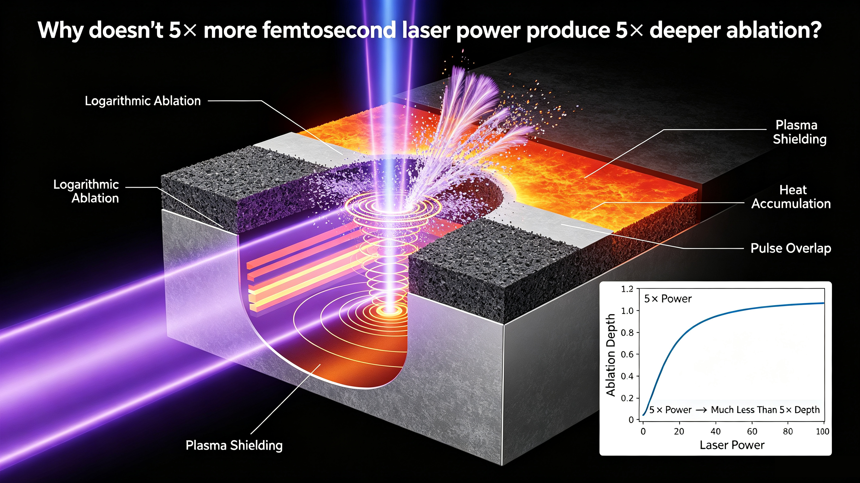
You are drilling a hole in copper with a femtosecond laser.
You increase the pulse energy from 1 μJ to 5 μJ—a fivefold increase.
But the measured ablation depth increases by only 30%.
You increase the pulse energy further to 10 μJ, expecting even deeper ablation.
Instead, the ablation depth becomes smaller.
Is the optical path drifting? Is the laser unstable?
If the experiment is repeated several times and produces the same result, the answer is probably no.
This counterintuitive behavior is a well-known challenge in high-repetition-rate femtosecond laser processing: increasing laser energy does not necessarily increase material removal efficiency. At sufficiently high fluence and repetition rates, several physical mechanisms can cause ablation efficiency to saturate or even decrease.
The three most important mechanisms are:
The logarithmic ablation law
Plasma and debris shielding
Heat accumulation
Together, they explain why simply increasing laser power is often not the best way to increase ablation depth or processing efficiency.
1. The Phenomenon: Higher Fluence, Lower Ablation Efficiency
Experimental data on femtosecond laser ablation of copper clearly demonstrate this non-linear behavior.
For a 1030 nm, 210 fs femtosecond laser operating under single-pulse conditions, increasing the fluence from approximately 0.52 J/cm² to 4.6 J/cm² increases the ablation efficiency from about 0.74 μm³/μJ to 5.3 μm³/μJ.
At first glance, this looks exactly as expected.
However, increasing the fluence further to approximately 9.9 J/cm² causes the ablation efficiency to fall to about 4.6 μm³/μJ.
The effect becomes even more obvious under multiple-pulse conditions.
For the first pulse, the reported ablation efficiency is approximately:
5.3 μm³/μJ
For the second pulse, it drops to:
2.0 μm³/μJ
That means the second pulse achieves only about 38% of the first-pulse efficiency.
The laser parameters have not changed.
What has changed is the environment created by the previous pulse: debris, plasma, vapor, and residual heat.
At high repetition rates, these effects can strongly influence subsequent pulses.
2. Mechanism 1: The Logarithmic Ablation Law
The first reason is fundamental.
Femtosecond laser ablation depth does not increase linearly with laser fluence.
A commonly used relationship is:
Lablation = δ × ln(F / Fth)
where:
Lablation is the ablation depth
δ is the effective penetration depth
F is the laser fluence
Fth is the ablation threshold
For copper, the source gives approximately:
δ ≈ 113 nm
and:
Fth ≈ 0.59 J/cm².
The logarithmic relationship has an important consequence.
When:
F = 2Fth
the ablation depth is:
L ≈ δ × ln(2) ≈ 0.69δ
When:
F = 10Fth
the ablation depth becomes:
L ≈ δ × ln(10) ≈ 2.3δ
Therefore, increasing fluence by a factor of 10 increases the predicted ablation depth by only about:
2.3 / 0.69 ≈ 3.3×
not 10×.
This is an intrinsic characteristic of the ablation process.
In other words:
Once the laser fluence is sufficiently above the ablation threshold, additional energy produces diminishing returns in ablation depth.
A significant fraction of the additional energy goes into accelerating and expanding the ablated material rather than simply increasing the depth of material removed.
3. Mechanism 2: Plasma and Debris Shielding
The second mechanism is particularly important for high-repetition-rate femtosecond processing.
When a femtosecond pulse ablates the target, it generates a plume containing:
Plasma
Nanoparticles
Vapor
Other ablation debris
This material remains above the target surface for a finite period of time.
The source gives a characteristic lifetime of approximately:
30 ns
for the debris/plasma cloud.
Now consider a high-repetition-rate laser.
At 64.7 MHz, for example, the interval between pulses is approximately:
15.5 ns
That is significantly shorter than the approximately 30 ns lifetime of the ablation plume.
Therefore, the next pulse arrives while the previous pulse's debris cloud is still present.
The cloud can partially absorb and scatter the incoming laser energy before it reaches the material surface.
A simplified expression for the transmitted fluence is:
Farrival = Fincident × exp(−Keff × C × L)
where:
Keff is the effective shielding coefficient
C is the debris-cloud concentration
L is the thickness of the debris cloud
The source gives an effective shielding coefficient for copper of approximately:
Keff ≈ 2.5 m²/g.
The practical consequence can be dramatic.
In the reported double-pulse copper ablation experiment, the second-pulse efficiency falls to only 38% of the first-pulse efficiency.
In other words, approximately 62% of the effective energy can be lost to shielding effects under those conditions.
4. An Unexpected Effect: Odd and Even Pulses Can Behave Differently
Plasma shielding can produce another counterintuitive phenomenon.
The ablation efficiency of:
1st, 3rd, 5th... pulses
can differ significantly from:
2nd, 4th, 6th... pulses.
Why?
Consider two consecutive pulses.
The first pulse produces substantial ablation and therefore generates a relatively dense debris cloud.
The second pulse encounters this dense cloud and is partially shielded, resulting in lower ablation.
Because the second pulse removes less material, it produces a less dense plume.
The third pulse therefore encounters less shielding and can achieve higher ablation efficiency again.
This creates an oscillating or quasi-bistable behavior between successive pulses.
The source reports that the difference between N = 2 and N = 3 can reach approximately 101% under the relevant experimental conditions.
This is particularly relevant when designing burst-mode or high-repetition-rate femtosecond processes.
5. Mechanism 3: Heat Accumulation
The third mechanism is thermal accumulation.
One of the major advantages of femtosecond laser processing is that energy can be deposited into electrons extremely rapidly, before the lattice has sufficient time to reach thermal equilibrium.
This enables highly localized, non-equilibrium material removal and can minimize the heat-affected zone.
However, this advantage has a practical limit.
At high repetition rates, the residual heat deposited by one pulse may not have enough time to dissipate before the next pulse arrives.
The result is cumulative heating.
As the deposited energy increases, the lattice temperature can rise substantially, and the material-removal mechanism can change.
5.1 Lower Ablation Threshold
One consequence of multiple-pulse exposure is a reduction in the effective ablation threshold, often associated with a laser-induced incubation effect.
The source gives the following representative values for copper:
Single-pulse threshold: 0.87 J/cm²
Multipulse saturation threshold: 0.18 J/cm²
The latter is approximately 21% of the single-pulse value.
This means that the material can become easier to ablate after repeated exposure.
But a lower threshold does not necessarily mean better processing quality.
5.2 Transition Toward Thermal Ablation
As the lattice temperature rises, the material-removal mechanism can shift away from predominantly non-thermal processes toward:
Melting + boiling
rather than highly localized non-equilibrium removal.
This can significantly degrade processing quality.
Typical consequences include:
Larger heat-affected zones
Microcracks
Thicker recast layers
Reduced surface quality
This leads to an important paradox:
Increasing laser power to exploit the advantages of femtosecond processing can eventually destroy those same advantages through thermal accumulation.
6. The Engineering Trade-Off: Power, Efficiency, and Quality
Femtosecond laser processing therefore involves a three-way trade-off between:
Laser energy → Ablation efficiency → Processing quality
The representative copper data can be summarized as follows:
| Fluence | Single-Pulse Efficiency | Second-Pulse Efficiency | Ablation Mode | Processing Quality |
|---|---|---|---|---|
| 0.52 J/cm² | 0.74 μm³/μJ | ~0.6 μm³/μJ | Mild ablation | Excellent |
| 4.6 J/cm² | 5.3 μm³/μJ | 2.0 μm³/μJ | Phase explosion | Moderate |
| 9.9 J/cm² | 4.6 μm³/μJ | <1.5 μm³/μJ | Thermal melting + shielding | Poor |
The important observation is that the optimum fluence is not the maximum available fluence.
Instead, there is an optimum region where material removal efficiency reaches a maximum.
The source identifies a theoretical optimum around:
Fopt ≈ e² × Fth>
and notes that the predicted value is close to the experimentally observed peak near 4.6 J/cm² under the referenced conditions.
Once the fluence exceeds the optimum region, additional energy increasingly contributes to plume expansion, debris ejection, shielding, and thermal accumulation rather than efficient material removal.
7. Repetition Rate Changes Everything
Laser repetition rate determines how much time the system has to recover between pulses.
Consider the following representative conditions:
| Repetition Rate | Pulse Interval | Approx. Plasma Lifetime | Shielding Risk | Thermal Accumulation Risk |
|---|---|---|---|---|
| 1 kHz | 1 ms | ~30 ns | Negligible | Low |
| 100 kHz | 10 μs | ~30 ns | Low | Moderate |
| 1 MHz | 1 μs | ~30 ns | Low | High |
| 64.7 MHz | 15.5 ns | ~30 ns | Severe | Severe |
At 1 kHz, the 1 ms interval is vastly longer than the characteristic plasma lifetime.
The plume has plenty of time to dissipate.
At 64.7 MHz, however, the pulse interval is only about 15.5 ns, shorter than the approximately 30 ns plume lifetime.
The next pulse therefore arrives while the shielding cloud is still present.
This is why simply increasing repetition rate is not necessarily an efficient way to increase material removal rate.
8. How to Find the "Sweet Spot"
The goal of process optimization is not to maximize laser power.
It is to find the operating region where:
Ablation efficiency × processing quality
is maximized.
Several practical strategies can help.
Strategy 1: Do Not Automatically Use Maximum Fluence
The logarithmic ablation relationship means that increasing fluence eventually produces diminishing returns.
The source proposes selecting the fluence around the theoretically optimal region rather than simply maximizing pulse energy.
The basic workflow is:
Measure the material's ablation threshold → calculate the target fluence → experimentally identify the optimum region.
The exact optimum should ultimately be determined experimentally for the specific material, pulse duration, wavelength, focusing condition, repetition rate, and scanning configuration.
9. Strategy 2: Reduce Repetition Rate or Use Burst Mode
If plasma shielding is a major limitation, increasing the interval between pulses can help.
When the pulse interval is sufficiently longer than the characteristic plasma lifetime, shielding is greatly reduced.
For MHz-class systems, burst-mode operation may provide another option.
Instead of continuously delivering pulses at the maximum repetition rate, pulses can be grouped into controlled bursts with cooling intervals between bursts.
The source specifically discusses a three-pulse burst as a potentially useful configuration under the referenced experimental conditions.
The appropriate burst structure, however, should be optimized experimentally rather than treated as a universal setting.
10. Strategy 3: Use Assist Gas to Remove the Debris Cloud
Another approach is to physically remove the plasma and debris plume using an assist gas.
Possible configurations include:
Coaxial gas flow
Side-flow gas jets
Inert gases such as:
Argon (Ar)
Helium (He)
can be used.
The source notes that helium can provide stronger plume-clearing performance because of its lower mass and higher achievable flow velocity.
A gas flow velocity on the order of 10 m/s is cited as sufficient to significantly reduce shielding under the referenced conditions.
However, excessive gas flow can disturb the focused laser beam and affect beam quality, so gas-flow optimization is necessary.
11. Strategy 4: Optimize Scan Speed and Pulse Overlap
For scanning applications, pulse overlap is another critical process parameter.
High pulse overlap means that successive pulses repeatedly interact with nearly the same region.
This increases the probability of thermal accumulation.
The source notes that for metals with a characteristic thermal diffusion time of approximately 100 ns, significant thermal accumulation can begin when pulse overlap exceeds roughly 70% under the relevant conditions.
Therefore, reducing pulse overlap—by:
Increasing scan speed
Reducing repetition rate
can be one of the most direct ways to preserve a predominantly non-equilibrium ablation regime.
12. The Key Lesson: More Power Is Not Always More Productivity
The most intuitive approach to increasing laser processing speed is:
Increase the laser power.
But femtosecond laser ablation does not necessarily behave this way.
Three mechanisms impose practical limits:
1. Logarithmic ablation
Ablation depth increases logarithmically with fluence rather than linearly.
A tenfold increase in fluence does not produce a tenfold increase in ablation depth.
2. Plasma shielding
At high repetition rates, debris generated by earlier pulses can absorb and scatter energy from subsequent pulses.
The second-pulse efficiency can fall dramatically under strong shielding conditions.
3. Thermal accumulation
When residual heat cannot dissipate between pulses, the material can gradually transition from highly localized non-equilibrium ablation toward thermal melting and boiling.
Processing quality then deteriorates.
13. Conclusion
If increasing femtosecond laser power by 5× produces only a modest increase in ablation depth—or if increasing the energy further actually makes the ablation shallower—the problem may not be the laser system.
It may simply be that you have crossed the optimum process window.
The key principles are:
1. Ablation depth follows a logarithmic relationship with fluence.
More energy produces diminishing returns.
2. High repetition rates can cause plasma and debris shielding.
The products of one pulse can partially block the next pulse.
3. Excessive pulse overlap can cause thermal accumulation.
The material may gradually lose the non-equilibrium processing advantages associated with femtosecond pulses.
Therefore:
The key to efficient femtosecond laser processing is not maximum power—it is the right combination of fluence, repetition rate, pulse overlap, scanning speed, and cooling time.
In practical process development, the objective should be to identify the sweet spot where material removal efficiency and processing quality are both optimized.
More laser power is not necessarily the answer.
Sometimes, giving the material more time to recover between pulses is more effective than adding more power.