
 EN
EN ES
ES ITA
ITA DE
DE FR
FRTEC Temperature Control: Why a ±0.01°C Laser Can Still Drift 50 pm

Why Does a Laser Wavelength Drift 50 pm When TEC Accuracy Is ±0.01°C?
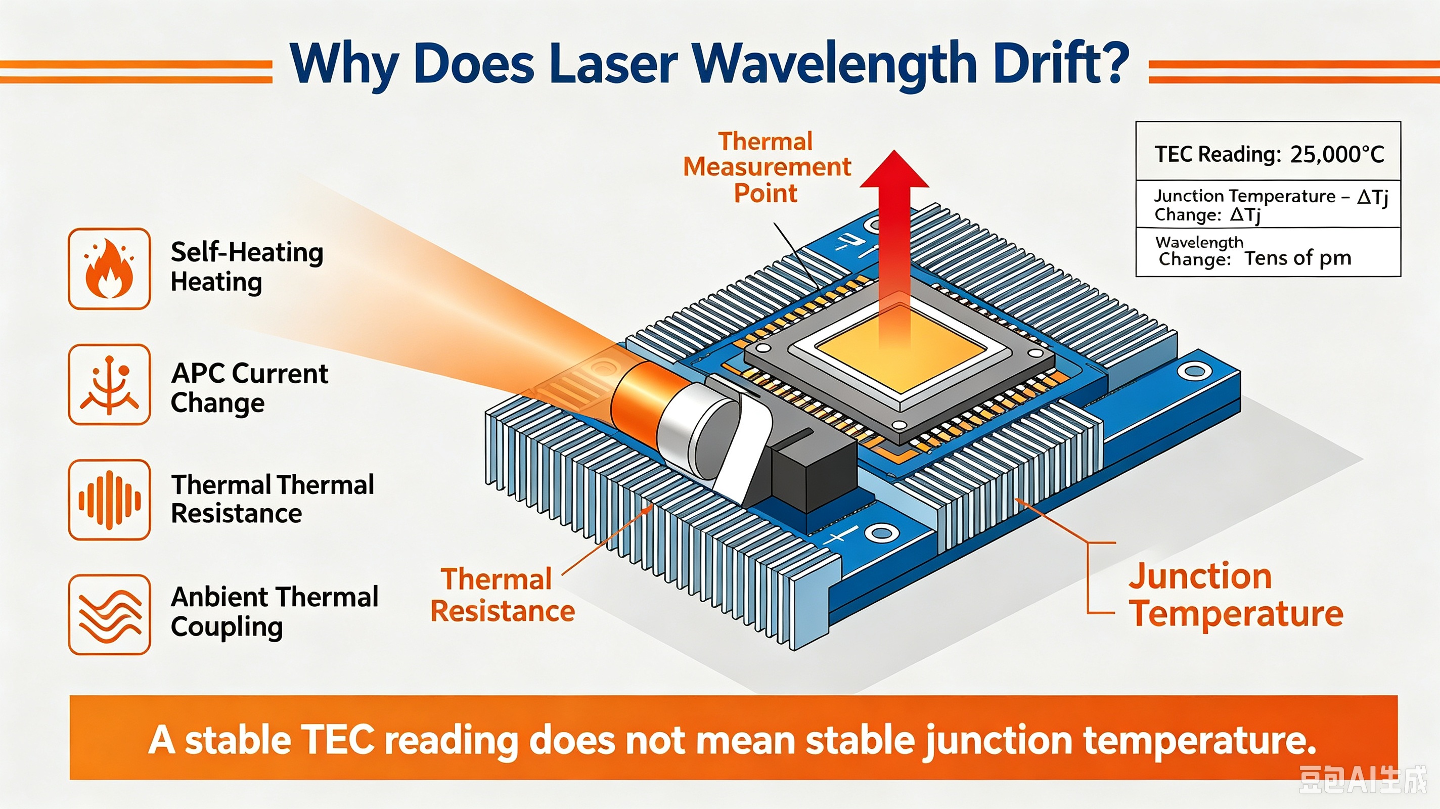
The TEC controller display looks perfect:
Temperature: 25.00°C ±0.01°C
You assume the laser temperature must therefore be extremely stable.
But then you look at the optical spectrum analyzer.
The DFB laser wavelength has drifted by 50 pm.
How can a laser wavelength move by 50 pm when the TEC claims temperature control accuracy of only ±0.01°C?
The answer is surprisingly simple:
The TEC is controlling the temperature where its sensor is located—not necessarily the temperature of the laser chip.
Between the thermistor and the laser chip are several thermal interfaces:
TEC → ceramic substrate → package base → solder layer → submount → laser chip
Every interface has thermal resistance.
At the same time, the laser chip generates its own heat, and the package can receive heat directly from the surrounding environment.
Therefore, the temperature reported by the TEC sensor can remain extremely stable while the actual laser-junction temperature continues to change.
±0.01°C Does Not Mean ±0.01°C at the Laser Junction
In a typical TEC-controlled laser package, the temperature sensor is usually an NTC thermistor located on or near the TEC cold side.
Depending on the package design, the sensor may be mounted:
on the ceramic substrate of the TEC
near the laser package base
close to the submount
or at another location selected for temperature control
The sensor therefore does not necessarily measure the actual temperature of the semiconductor junction.
The thermal path can be simplified as:
Thermistor
↓
TEC cold-side ceramic
↓
Package base
↓
Solder / bonding layer
↓
Submount
↓
Laser chip
Each layer introduces thermal resistance.
The original source notes that the thermal resistance from the TEC cold side to the laser chip in a typical butterfly package can be on the order of several K/W, depending strongly on package construction and assembly.
This distinction is critical.
A TEC controller can maintain its sensor at:
while the laser junction is actually at:
The two temperatures can differ significantly even though the controller reports excellent temperature stability.
The Hidden Temperature Rise: Laser Self-Heating
The laser chip is not a passive thermal load.
A DFB laser consumes electrical power during operation.
The approximate electrical power is:
where:
is the forward current
is the forward voltage
For example, if:
and
then:
or approximately 150 mW.
The resulting temperature rise can be estimated as:
where is the relevant thermal resistance between the heat-generating region and the controlled temperature point.
If the effective thermal resistance were 10 K/W and the dissipated power were 200 mW:
The TEC sensor could therefore report approximately 25°C while the laser chip operates at a substantially higher temperature.
The exact temperature difference depends on the package, thermal path, optical output power, current, voltage, and mounting conditions.
Why Does a Small Junction Temperature Change Move the Wavelength?
DFB laser wavelength is strongly temperature dependent.
A simplified relationship is:
The source uses a representative temperature coefficient of approximately:
for a DFB laser.
Using this representative value:
Therefore:
So a 50 pm wavelength drift can correspond to only about:
0.5°C of effective laser temperature change.
This is already enough to explain the apparent contradiction.
The TEC sensor may be stable to ±0.01°C, while the actual junction temperature changes by several tenths of a degree.
The two numbers describe different physical locations.
A More Important Problem: Bias Current Can Change the Junction Temperature
One of the easiest ways to create this effect is to change the laser drive current.
Consider a DFB laser whose current changes from:
80 mA → 100 mA
If the forward voltage remains approximately in the same range, the electrical power increases.
For example, the source estimates an increase from approximately 120 mW to 160 mW under representative operating conditions.
That is an additional:
of dissipated power.
If the relevant thermal resistance is:
then:
Using the representative wavelength coefficient:
or:
That is already close to the 50 pm wavelength drift observed in the original example.
The important lesson is:
A wavelength drift caused by current-dependent self-heating does not necessarily mean the TEC temperature control has failed.
The TEC may be doing exactly what it was designed to do.
It is simply regulating the temperature at the sensor location while the laser junction experiences a different thermal condition.
APC Can Make the Problem Harder to Notice
This becomes particularly important when the laser operates under Automatic Power Control (APC).
An APC loop continuously adjusts the laser drive current to maintain a target optical output power.
If the laser's optical efficiency changes because of temperature, aging, or operating conditions, the APC loop may change the drive current.
That creates a feedback chain:
Temperature / optical efficiency changes
↓
APC adjusts laser current
↓
Electrical power changes
↓
Laser self-heating changes
↓
Junction temperature changes
↓
Laser wavelength shifts
The TEC controller may still report almost exactly the same temperature.
This is why monitoring only the TEC temperature can give an incomplete picture of laser wavelength stability.
The original source specifically recommends monitoring laser current and output power together when investigating this type of wavelength drift.
Ambient Temperature Can Bypass the TEC Control Loop
There is another thermal path that is easy to overlook.
The laser package is exposed to the surrounding environment.
When ambient temperature increases, heat can enter the package directly through:
package walls
electrical leads
mounting structures
heat sinks
mechanical interfaces
This creates a thermal path from the environment to the laser chip that is not necessarily measured by the TEC thermistor.
The TEC still attempts to maintain its controlled temperature.
However, its cooling capacity is finite.
As ambient temperature increases, the TEC hot-side temperature also increases, making it more difficult to maintain the same temperature difference between the TEC cold and hot sides.
The original source points out that small TECs can experience significant changes in cooling performance as the temperature difference across the device increases.
This produces an important engineering distinction:
Sensor accuracy is not the same thing as system-level thermal stability.
A temperature sensor can be extremely accurate while the laser junction remains sensitive to environmental changes.
Sensor Accuracy vs. Junction Temperature Stability
This is perhaps the most important concept in the entire problem.
Consider three different specifications:
1. Temperature Sensor Accuracy
How accurately does the thermistor or temperature sensor measure the temperature at its own location?
2. TEC Control Stability
How well can the TEC controller maintain the temperature at the sensor location?
3. Laser Junction Temperature Stability
How much does the actual semiconductor junction temperature change?
These are not equivalent specifications.
A system could theoretically achieve:
at the sensor while the junction temperature varies by:
or more.
The difference comes from the thermal network between the sensor and the heat-generating device.
This is why simply improving the thermistor resolution does not automatically produce better laser wavelength stability.
Four Practical Tests to Find the Real Cause
If you observe significant wavelength drift despite excellent TEC temperature stability, the following diagnostic sequence is useful.
1. Measure Laser I-V Characteristics
Measure the laser's:
forward current
forward voltage
electrical power
Calculate:
Then vary the bias current and record the corresponding wavelength shift.
This allows you to estimate the effective thermal response of the laser package.
The original source recommends using current-induced wavelength changes to estimate the effective thermal resistance.
2. Monitor Optical Power and APC Current
Use an external optical power meter to monitor the actual laser output.
At the same time, record:
laser current
TEC temperature
wavelength
If the APC loop changes current while the TEC temperature remains stable, check whether the wavelength changes at the same time.
A correlation between:
current → electrical power → wavelength
is strong evidence of junction self-heating.
3. Perform an Ambient Temperature Step Test
Change the ambient temperature by a controlled amount—for example, a +10°C temperature step.
After the TEC reaches its controlled steady state, measure the remaining wavelength shift.
If the TEC temperature appears stable but the wavelength continues to move significantly, investigate the direct thermal path from the package and environment to the laser chip.
The source proposes this type of environmental step test as a practical diagnostic method.
4. Consider Wavelength Locking Instead of Temperature Control Alone
If the application requires extremely tight wavelength stability, controlling temperature alone may not be sufficient.
A wavelength locker, such as an etalon-based wavelength-locking system, can use the actual optical wavelength as the feedback variable.
The control loop then becomes:
Measure wavelength → compare with target → adjust laser operating conditions
instead of:
Measure package temperature → assume wavelength is stable
This directly controls the parameter that the optical system actually cares about.
The source specifically identifies wavelength locking as an alternative approach when wavelength stability is the primary requirement.
What Should You Measure When Wavelength Stability Matters?
If the goal is to evaluate a DFB laser for wavelength-sensitive applications, measuring TEC temperature alone is insufficient.
A more complete measurement set should include:
| Parameter | Why it matters |
|---|---|
| TEC sensor temperature | Indicates controlled thermal point |
| Laser drive current | Determines electrical self-heating |
| Laser forward voltage | Helps calculate electrical power |
| Optical output power | Shows APC behavior |
| Optical wavelength | Direct performance parameter |
| Ambient temperature | Reveals environmental coupling |
| TEC current | Indicates cooling/heating effort |
The most useful measurement is often the correlation between these parameters.
For example:
Laser current increases
→ electrical power increases
→ junction temperature rises
→ wavelength shifts
while:
TEC sensor temperature remains nearly unchanged
That pattern is much more informative than looking at the TEC temperature trace alone.
The Key Engineering Lesson
A TEC specification of:
does not mean that the laser junction temperature is stable to ±0.01°C.
The TEC controller is regulating the temperature at a particular physical location.
Between that location and the laser chip are:
thermal resistance
package materials
solder and bonding layers
submounts
heat spreading structures
At the same time, the laser chip generates heat, while the surrounding environment provides additional thermal paths.
Therefore:
Excellent TEC sensor stability does not automatically guarantee excellent laser wavelength stability.
A 50 pm wavelength shift can correspond to only a fraction of a degree of effective junction-temperature change, depending on the laser's wavelength-temperature coefficient.
The right question is therefore not:
“Why can't my TEC hold ±0.01°C?”
It is:
“How closely does the temperature measured by the TEC sensor track the actual laser junction temperature?”
For wavelength-critical applications such as DWDM, coherent communications, optical test equipment, and precision photonic systems, this distinction is fundamental.
The TEC may be controlling the right temperature from the controller's perspective—but the wrong temperature from the wavelength-stability perspective.