
 EN
EN ES
ES ITA
ITA DE
DE FR
FREDFA Gain Overshoot: Why ±0.5 dB Can Become 3 dB During WDM Channel Add/Drop

Why Does an EDFA Rated at ±0.5 dB Overshoot by 3 dB During WDM Channel Add/Drop?
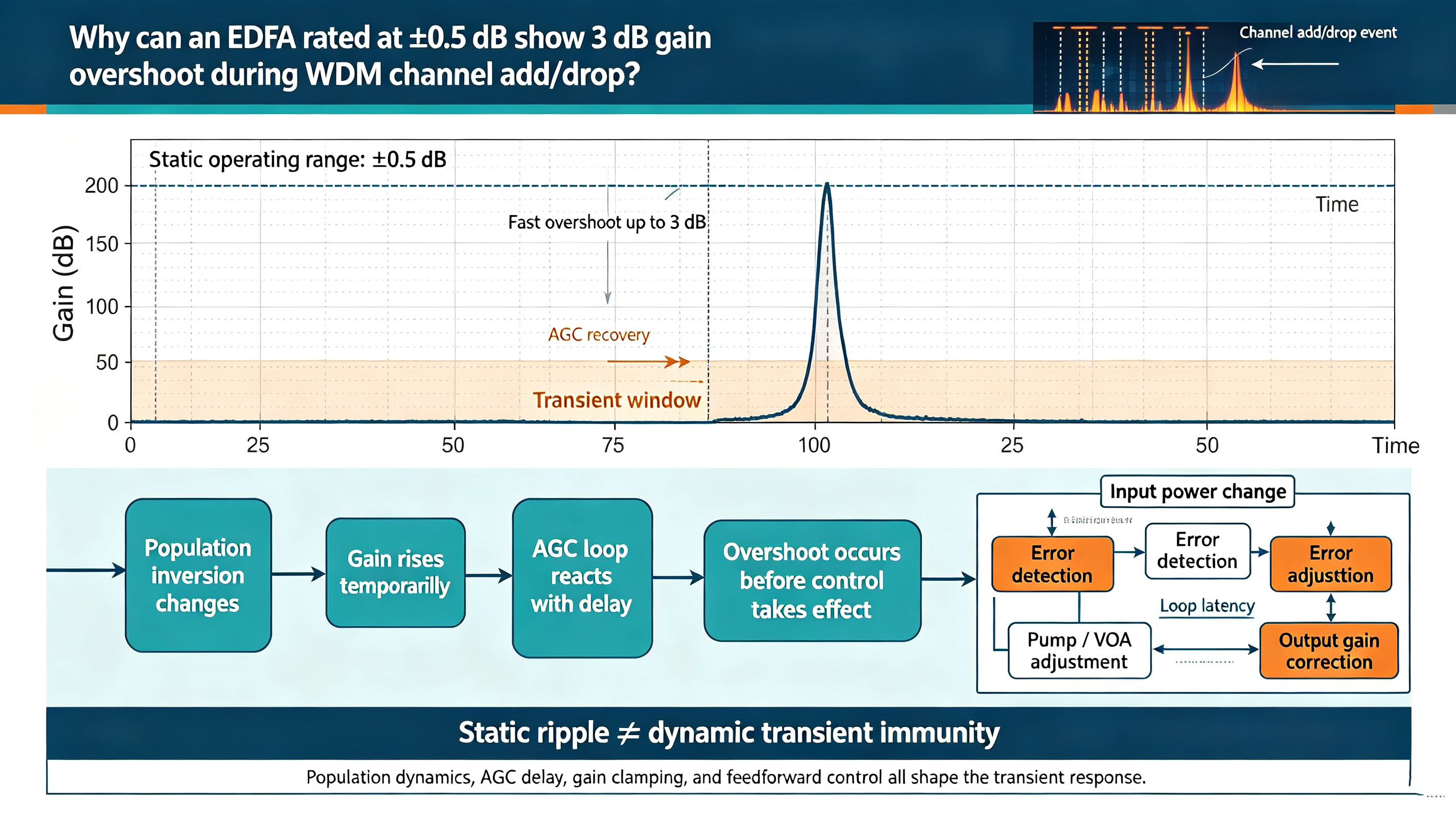
Your EDFA datasheet says:
Gain stability: ±0.5 dB
So you expect the output power of the remaining WDM channels to stay within roughly ±0.5 dB when one channel is removed.
Then you switch off the eighth WDM channel.
The result is unexpected.
The remaining channels suddenly jump by approximately 3 dB.
Why can an EDFA specified for ±0.5 dB experience a 3 dB power excursion?
The answer is that ±0.5 dB is normally a steady-state specification, while WDM channel add/drop is a dynamic event.
The amplifier behaves very differently when all channels remain stable than when several channels suddenly disappear.
This difference becomes especially important in dynamically reconfigurable WDM networks, where channels can be added or dropped within a short time.
±0.5 dB Is Not a Transient Performance Guarantee
A typical EDFA gain specification is measured under controlled conditions:
input optical power is stable
channel loading remains constant
pump power is regulated
temperature is controlled
the amplifier has reached steady state
Under these conditions, the gain can remain very stable.
But consider what happens when one WDM channel suddenly disappears.
Before the channel is removed:
Pump power → erbium excitation → signal amplification
The pump continuously creates population inversion in the erbium-doped fiber, while the optical signals consume that stored excitation through stimulated emission.
The system reaches a dynamic equilibrium.
Now remove one channel.
The signal-induced depletion of the erbium population suddenly decreases, but the pump does not necessarily stop at the same instant.
The stored population therefore increases.
The gain available to the remaining channels temporarily rises.
The result is a transient gain overshoot.
The original source describes this process as a consequence of the finite response time associated with the erbium upper-state population.
This is the fundamental reason that a steady-state gain specification cannot be directly applied to a channel add/drop event.
The Physical Mechanism: Why Does Removing One Channel Increase the Gain of the Others?
The key quantity is the population inversion of the erbium ions.
The simplified process is:
Pump photons
↓
Excite Er³⁺ ions
↓
Build population inversion
↓
Signal photons consume the inversion
↓
Stable optical gain
Now remove one channel.
The total signal power traveling through the EDFA decreases.
Therefore:
Signal loading ↓
→ stimulated emission ↓
→ population inversion ↑
→ available gain ↑
→ remaining channels experience an overshoot
The erbium upper-state population does not instantly return to the new equilibrium.
This finite response produces the transient.
When a channel is added, the opposite occurs.
The new channel suddenly consumes part of the available population inversion:
Signal loading ↑
→ population inversion ↓
→ gain available to existing channels ↓
→ existing channels experience a transient undershoot.
Therefore:
Channel drop tends to produce gain overshoot, while channel add tends to produce gain undershoot.
Why Can a Single Channel Cause Several dB of Overshoot?
The effect becomes more severe when the total number of WDM channels is small.
Suppose an EDFA is operating with eight channels.
Removing one channel represents:
of the total channel count.
That is a significant change in the optical loading of the amplifier.
If the system contains 40 channels, removing one channel represents only:
of the total channel count.
The relative perturbation is therefore much smaller.
However, the worst-case event can be much more severe.
For example, a system that transitions from many active channels to only a few remaining channels can experience a very large change in gain loading.
The source cites simulation work showing that transient overshoot becomes increasingly significant as the number of active WDM channels decreases, with reported overshoot of approximately 2–5 dB in an eight-channel system when one channel is dropped, and substantially larger excursions under severe channel-count reduction.
The exact value depends strongly on:
channel power
channel count
EDFA saturation level
pump power
amplifier design
gain-control strategy
transition speed
channel spacing and loading conditions
Therefore, the 3 dB value should be understood as an example of a realistic transient event, rather than a universal EDFA characteristic.
Why Doesn't AGC Prevent the Overshoot?
A natural question is:
“If the EDFA has automatic gain control, shouldn't it immediately compensate for the missing channel?”
Not necessarily.
An EDFA's Automatic Gain Control (AGC) loop needs to detect the input or output power change, process that information, and then adjust the pump power.
A simplified control loop looks like:
Input power changes
↓
Photodiode detects the change
↓
ADC samples the signal
↓
Digital controller calculates correction
↓
Pump current is adjusted
↓
EDFA gain returns toward its target
The entire feedback loop has finite latency.
The source estimates representative delays on the order of hundreds of microseconds when detection, ADC processing, digital processing, and pump-current control are considered together.
Meanwhile, the erbium population is already responding to the sudden change in signal loading.
Therefore:
The pump laser may be fast enough. The limitation can instead be the feedback loop that decides how the pump should change.
This is a classic control-system problem.
The amplifier's optical medium responds immediately to the change in channel loading, while the electronic controller needs time to detect and correct the disturbance.
Why Feedforward Control Can Help
A conventional AGC system is a feedback system.
It waits for the disturbance to occur, measures the resulting error, and then corrects it.
A feedforward system takes a different approach.
If the network controller already knows that a channel is about to be added or removed, the amplifier can be informed before the optical power actually changes.
The control sequence becomes:
Channel add/drop command
↓
Predict expected optical-power change
↓
Pre-adjust pump power
↓
Channel transition
↓
Reduced transient gain excursion
This can significantly reduce the initial error because the pump adjustment does not have to wait for the feedback loop to detect the disturbance.
The source identifies feedforward control as one of the approaches used to address transient gain effects.
All-Optical Gain Clamping: Another Approach
Another technique is all-optical gain clamping (AOGC).
The basic concept is to introduce an additional optical mechanism that consumes excess population inversion when the signal loading changes.
Instead of allowing the erbium population to rise significantly after a channel is removed, the gain-clamping mechanism absorbs part of the excess inversion.
Conceptually:
Channel drop
→ signal loading decreases
→ excess population inversion appears
→ gain-clamping mechanism consumes the excess
→ remaining-channel gain changes less
AOGC can therefore reduce transient gain excursions without relying entirely on the electronic AGC loop.
However, gain clamping itself has dynamic limitations.
The response depends on the optical cavity, relaxation dynamics, and implementation of the gain-clamping structure.
The source cites work showing that even with all-optical gain clamping, residual overshoot of approximately 1–2 dB can still occur under certain conditions.
So AOGC should not be interpreted as making the amplifier perfectly transient-free.
What Happens in Cascaded EDFAs?
Modern long-haul optical networks often contain multiple EDFAs.
This creates another important consideration.
When several EDFAs are cascaded, a transient created by one amplifier can propagate to the next amplifier.
However, the transient does not simply increase linearly at every stage.
The changing optical power modifies the saturation conditions of subsequent amplifiers, creating a complex interaction between stages.
The source cites research showing that cascading multiple EDFAs can shorten the overall transient duration because the disturbance propagates through the amplifier chain. In one reported five-stage configuration, the total transient duration was approximately one-fifth of the corresponding single-stage duration.
The important engineering lesson is:
Cascaded EDFAs should be analyzed as a dynamic system, not simply as independent steady-state gain blocks.
A 3 dB Overshoot Is Not Just “3 dB More Power”
A 3 dB power increase means approximately:
So a 3 dB overshoot represents a doubling of optical power.
That is significant in a high-speed optical communication system.
The problem is not merely that the receiver temporarily sees a stronger signal.
The sudden power excursion can interact with fiber nonlinearities and receiver operating margins.
For example, increased optical intensity can enhance nonlinear effects such as:
self-phase modulation (SPM)
cross-phase modulation (XPM)
four-wave mixing (FWM)
nonlinear phase accumulation
The source specifically highlights the relationship between a 3 dB power excursion and increased nonlinear effects in standard single-mode fiber.
Therefore, a transient lasting only milliseconds can still be important.
At 10 Gb/s:
A 10 ms transient corresponds to approximately:
bit periods.
In other words, the amplifier can remain in a transient state for an enormous number of bit intervals.
The event may therefore appear short from a human perspective while being extremely long from the perspective of a high-speed communication system.
Why the BER Can Suddenly Get Worse
A power overshoot can affect the link in several ways.
Receiver overload
The sudden increase in optical power can push the receiver or front-end electronics outside their intended operating range.
Nonlinear distortion
Higher optical power increases nonlinear phase effects in the transmission fiber.
OSNR and system-margin disturbance
The transient changes the instantaneous operating point of the optical link.
Burst errors
Even if the average BER over a long measurement interval appears acceptable, the short transient window can produce a concentrated burst of errors.
This is particularly important for systems where service continuity matters more than long-term average performance.
How Should You Test EDFA Transient Performance?
A steady-state optical spectrum measurement is not enough.
If you want to know whether an EDFA can handle WDM channel add/drop events, you need a dynamic test.
Step 1: Simulate Channel Add/Drop
Use an optical switch or equivalent setup to abruptly add or remove one or more WDM channels.
The source recommends using controlled channel transitions with sufficiently long intervals between events.
Step 2: Monitor the Remaining Channel with a Fast Detector
Measure the optical power of the remaining channel using:
a sufficiently fast photodetector
an oscilloscope
an optical power monitoring system
The goal is to capture the transient rather than only the final steady-state value.
Record:
initial power
peak overshoot
minimum undershoot
rise time
settling time
recovery time
Step 3: Test Both Add and Drop Events
Do not test only channel removal.
You should characterize both:
Channel DROP
→ gain overshoot
and
Channel ADD
→ gain undershoot
A complete transient specification should describe both directions.
When Should Transient Suppression Be Considered?
If the measured overshoot is several dB, the EDFA should not be evaluated solely against its steady-state gain specification.
The system designer should consider additional transient-control techniques.
Potential approaches include:
All-Optical Gain Clamping
Useful when fast optical suppression of population-inversion changes is required.
Feedforward Pump Control
Useful when the network controller knows the channel transition in advance.
Faster Gain-Control Loops
Reduce detection and control latency.
Channel Power Equalization
Reducing the power difference between active and newly added channels can reduce the severity of the disturbance.
Network-Level Transient Management
Coordinate ROADM, WSS, optical switches, and EDFA control rather than treating each amplifier independently.
For cascaded systems, transient suppression may be particularly important in the earlier amplifier stages because disturbances can propagate through the rest of the link.
The Key Engineering Lesson
An EDFA specification such as:
does not necessarily mean:
“The output power will never deviate by more than 0.5 dB under any operating condition.”
It generally describes performance under specified steady-state conditions.
A WDM channel add/drop event is fundamentally different.
When a channel suddenly disappears:
Signal loading ↓
→ erbium population inversion ↑
→ available gain ↑
→ remaining channels overshoot
When a channel suddenly appears:
Signal loading ↑
→ population inversion ↓
→ available gain ↓
→ existing channels undershoot
The electronic AGC loop then has to detect and correct the disturbance, but its response is finite.
Therefore:
±0.5 dB is a steady-state gain specification—not a guarantee of ±0.5 dB transient behavior during channel add/drop.
If your EDFA shows a 3 dB overshoot when a WDM channel is removed, the right question is not simply:
“Why doesn't the EDFA meet its ±0.5 dB specification?”
Instead, ask:
“Was the ±0.5 dB specification measured under the same dynamic channel-loading conditions as the actual network?”
That distinction is critical when designing, testing, and troubleshooting dynamically reconfigurable WDM systems.