
 EN
EN ES
ES ITA
ITA DE
DE FR
FRDFB Laser Linewidth: Why 1 MHz Can Become 10 MHz in a Real System

Why Does a 1 MHz DFB Laser Have a 10 MHz Linewidth in Your System?
Two Critical Factors to Check: Optical Feedback and Drive-Current Noise
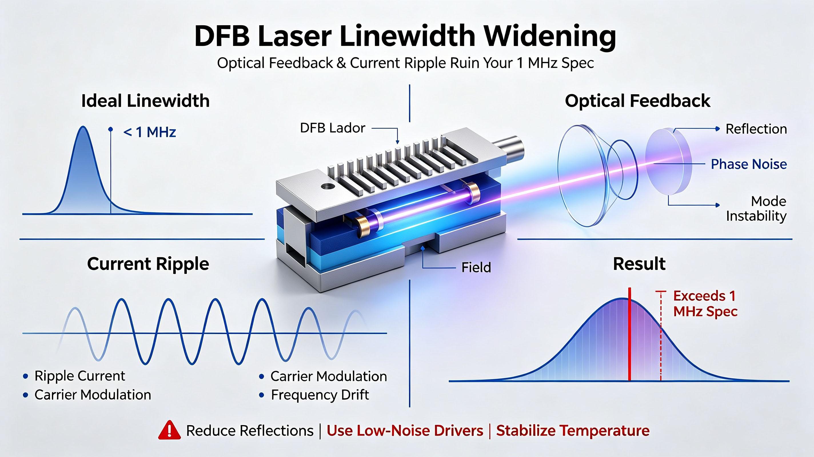
The datasheet says “linewidth ≤ 1 MHz.”
You install the DFB laser, connect the fiber, set up a delayed self-heterodyne measurement—and the measured linewidth is 10 MHz.
Is the laser chip defective? Is the measurement instrument wrong?
Not necessarily.
The more likely explanation is that the 1 MHz datasheet linewidth was measured under highly controlled laboratory conditions, while your actual system is exposed to optical feedback, drive-current noise, mechanical vibration, and other disturbances.
In particular, optical feedback and current noise can significantly broaden the linewidth of a DFB laser.
This article examines why the linewidth specified in a DFB laser datasheet can differ substantially from the linewidth measured in a real optical system, and why two factors—optical feedback and drive-current noise—should be among the first things to investigate.
1. How Is the 1 MHz Datasheet Linewidth Measured?
The linewidth specified on a DFB laser datasheet is not simply a random number.
It generally represents the performance measured under carefully controlled experimental conditions designed to minimize external disturbances.
Typical test conditions may include:
Optical isolation
The laser output is connected to a high-isolation optical isolator, typically with isolation greater than 40 dB.
The purpose is to prevent reflected light from returning to the laser cavity and disturbing the laser's optical field.
Ultra-low-noise current drive
A low-noise current source is used to minimize current fluctuations.
The source describes a typical laboratory condition of less than 100 nA current ripple, together with precision temperature control on the order of ±0.001°C.
Delayed self-heterodyne measurement
A common linewidth measurement technique is the delayed self-heterodyne method.
The laser output is split into two optical paths:
One path passes through a fiber delay of several tens of kilometers.
The other path passes through an AOM and is frequency-shifted by approximately 80 MHz.
The two signals are then combined and detected to generate a beat signal.
The resulting power spectrum can be analyzed to determine the linewidth from its full width at half maximum (FWHM).
Vibration isolation
The optical setup is typically placed on a vibration-isolated optical table to minimize frequency fluctuations caused by mechanical vibration.
In other words, the datasheet linewidth is closer to a best-case laboratory value than a guaranteed value under arbitrary system conditions.
2. The First Major Culprit: Optical Feedback
One of the most important causes of DFB linewidth broadening is optical feedback, also known as an external-cavity or parasitic-cavity effect.
When a small portion of the laser output is reflected back toward the laser cavity, the reflected optical field can interfere with the field inside the laser.
The external reflection effectively creates an additional optical cavity outside the laser itself.
Even a relatively small amount of feedback can have a significant effect.
According to the source material, when the feedback coefficient reaches approximately 1%, or around −20 dB, the laser linewidth can broaden by approximately an order of magnitude.
A nominal:
1 MHz → approximately 10 MHz
change can therefore occur under sufficiently strong optical feedback.
This is why optical feedback should be one of the first things to investigate when a DFB laser shows a linewidth substantially higher than its datasheet value.
2.1 Where Does Optical Feedback Come From?
In a real optical system, reflected light can originate from many locations.
Common sources include:
Fiber connector reflections
Even commonly used low-reflection connectors such as FC/APC are not perfectly reflection-free.
The source notes that FC/APC connectors can have return loss around −60 dB, which may still be relevant in particularly sensitive applications.
Residual reflections from optical components
Components such as:
WDM devices
Optical isolators
Circulators
Other passive optical components
can introduce residual reflections into the optical path.
Fusion splices
Poor-quality fusion splices can also introduce reflections. The source gives a typical range of approximately −40 to −50 dB for problematic connections.
Uncoated optical surfaces
Any glass surface without an appropriate anti-reflection coating can potentially produce an unwanted reflection.
The important point is that the reflected power does not have to be large to affect a narrow-linewidth laser.
3. The Second Major Culprit: Drive-Current Noise
The second factor that deserves close attention is drive-current noise.
The optical frequency of a DFB laser is highly sensitive to its drive current.
When the drive current changes, the carrier density in the active region changes. This affects the refractive index through carrier-induced effects and ultimately changes the output frequency selected by the distributed-feedback grating.
This behavior can be described using the current-to-frequency tuning coefficient:
dν/dI
For a typical DFB laser, the source gives a representative tuning coefficient of approximately:
0.5–3 GHz/mA
The corresponding frequency fluctuation can be approximated as:
Δν = (dν/dI) × ΔI
where:
Δν is the frequency fluctuation
dν/dI is the current-to-frequency tuning coefficient
ΔI is the drive-current fluctuation
3.1 A Surprisingly Small Current Ripple Can Matter
Consider a DFB laser with a current-to-frequency tuning coefficient of:
1 GHz/mA
If the current source has an RMS ripple of only:
1 μA
then:
Δν = 1 GHz/mA × 1 μA ≈ 1 MHz
Therefore, a current fluctuation of only 1 μA RMS can correspond to approximately 1 MHz of frequency fluctuation under these assumed conditions.
This illustrates why the current source cannot be treated as a secondary component in a narrow-linewidth laser system.
The source notes that typical commercial laser diode drivers (LDDs) may have current ripple on the order of 10–100 μA, meaning that drive-current noise alone can potentially contribute substantially to linewidth broadening.
For a system targeting MHz-level linewidth, the quality of the laser driver can therefore be just as important as the laser chip itself.
4. The Physical Origin of DFB Laser Linewidth
To understand why DFB lasers have finite linewidth even under ideal conditions, it is useful to start with the Schawlow–Townes linewidth limit.
The Schawlow–Townes equation describes the fundamental quantum-limited linewidth of a laser:
ΔνST = πhν(Δνc)² / Pout
where:
ΔνST is the Schawlow–Townes linewidth
hν is the photon energy
Δνc is the cavity bandwidth
Pout is the optical output power
The equation indicates that:
A narrower cavity bandwidth can reduce the fundamental linewidth.
Higher output power can reduce the fundamental linewidth.
For a representative DFB laser with approximately 10 mW output power and a cavity bandwidth of approximately 100 GHz, the source estimates a Schawlow–Townes limit in the sub-kHz range.
This is much narrower than the MHz-level linewidth commonly observed in practical semiconductor lasers.
So what accounts for the difference?
5. Henry's Linewidth Enhancement Factor
A key contribution comes from amplitude–phase coupling in semiconductor lasers.
Carrier-density fluctuations do not only change the optical gain and therefore the amplitude of the laser field. They can also change the refractive index, producing phase fluctuations.
This amplitude–phase coupling is commonly described by the Henry linewidth enhancement factor, α.
The linewidth can be expressed approximately as:
Δν = (1 + α²) × ΔνST
where α is the Henry linewidth enhancement factor.
The source gives a representative α range of approximately:
α ≈ 3–6
Therefore:
1 + α² ≈ 10–37
This means that the actual intrinsic linewidth can be one to two orders of magnitude larger than the ideal Schawlow–Townes limit.
This helps explain why a practical DFB laser can have an intrinsic linewidth in the MHz range even though the fundamental quantum-limited value may be much lower.
Once external disturbances such as optical feedback and current noise are added, the measured linewidth can increase significantly further.
6. A Practical Example: From 1 MHz to 30 MHz
Consider a representative 1550 nm DFB laser.
The source provides the following simplified measurement sequence:
| Test Condition | Measured Linewidth | Broadening |
|---|---|---|
| Datasheet-like conditions: optical isolation + low-noise current source + vibration isolation | ~1 MHz | 1× |
| Optical isolator removed; connector reflection ~−30 dB | ~5 MHz | 5× |
| Standard LDD used; current ripple ~10 μA RMS | ~15 MHz | 15× |
| Vibration isolation removed; desktop environment with fan vibration | ~30 MHz | 30× |
The example demonstrates how quickly the measured linewidth can deteriorate when key environmental controls are removed.
Importantly, these effects should not simply be assumed to add linearly in every real system.
The source notes that the example treats the effects independently, while actual systems can exhibit nonlinear interactions between different noise and feedback mechanisms, potentially producing even worse results.
7. How Should You Build a Linewidth Budget?
Once the mechanisms behind linewidth broadening are understood, system design should work backward from the datasheet specification.
The source proposes a practical linewidth budget:
Δνsystem = Δνspec × (5–20)
where:
Δνsystem is the estimated system linewidth budget
Δνspec is the datasheet linewidth
The 5–20× margin depends on the optical isolation and current-source noise level.
For example, if a system requires:
Linewidth < 20 MHz
it may be prudent to select a DFB laser with a specified linewidth of:
≤ 2 MHz
rather than selecting a device specified at 20 MHz.
The reasoning is that the actual system linewidth may be significantly broader than the datasheet value once optical feedback, electrical noise, vibration, and other practical factors are introduced.
8. Two Things to Check First When Linewidth Is Too Wide
If a DFB laser is specified at 1 MHz but your measurement shows 10 MHz or more, two areas deserve immediate attention.
Check 1: Optical Feedback
Inspect the entire optical path for unwanted reflections.
Pay particular attention to:
Fiber connectors
WDMs
Isolators
Circulators
Fusion splices
Uncoated optical surfaces
External optical components
Adding an appropriate optical isolator and improving return-loss performance can significantly reduce the influence of reflected light.
Check 2: Drive-Current Noise
Measure the actual current noise of the laser driver rather than relying only on its nominal current accuracy.
For a narrow-linewidth DFB laser, current ripple can translate directly into frequency modulation through the laser's current-to-frequency tuning coefficient.
Even microamp-level current fluctuations can therefore become significant when the target linewidth is only a few MHz.
9. Datasheet Linewidth Is a Reference—Not a Guarantee
One of the most common mistakes in narrow-linewidth laser system design is treating the datasheet linewidth as the linewidth that will automatically be obtained in the final system.
A datasheet value such as:
“Linewidth ≤ 1 MHz”
should instead be interpreted as a performance value obtained under specified measurement conditions.
Your actual system may have:
Optical reflections
Drive-current ripple
Temperature fluctuations
Mechanical vibration
Additional optical components
Imperfect connectors and splices
All of these can contribute to the final measured linewidth.
Therefore, the correct question is not simply:
“What is the linewidth of this DFB laser?”
but rather:
“What linewidth can I expect from this DFB laser in my complete system?”
That distinction is critical when designing narrow-linewidth optical sources.
10. Conclusion
A DFB laser specified at 1 MHz linewidth can show a measured linewidth of 10 MHz or even tens of MHz in a practical system without necessarily indicating that the laser chip or measurement instrument is defective.
The most important factors to investigate first are:
1. Optical feedback
Even relatively small reflections can disturb the laser cavity and broaden the linewidth.
2. Drive-current noise
Because the DFB laser frequency is sensitive to drive current, current ripple can be converted into frequency modulation and contribute directly to linewidth broadening.
Beyond these two factors, the intrinsic semiconductor-laser linewidth is also influenced by amplitude–phase coupling, described by the Henry linewidth enhancement factor.
The key engineering lesson is:
Treat the datasheet linewidth as a best-case reference, not as a guaranteed system-level performance value.
When designing a narrow-linewidth DFB laser system, reserve sufficient linewidth margin, minimize optical feedback, use a low-noise current driver, and control mechanical and thermal disturbances.
For practical system design, the source recommends budgeting the actual system linewidth at approximately 5–20 times the datasheet specification, depending on the optical isolation and current-source noise performance.
A 1 MHz DFB laser does not necessarily become a “bad” 10 MHz laser.
Sometimes, the laser is simply telling you that the rest of the system needs to be checked.