
 EN
EN ES
ES ITA
ITA DE
DE FR
FRPM Fiber Splicing: Why Extinction Ratio Drops from 40 dB to 25 dB

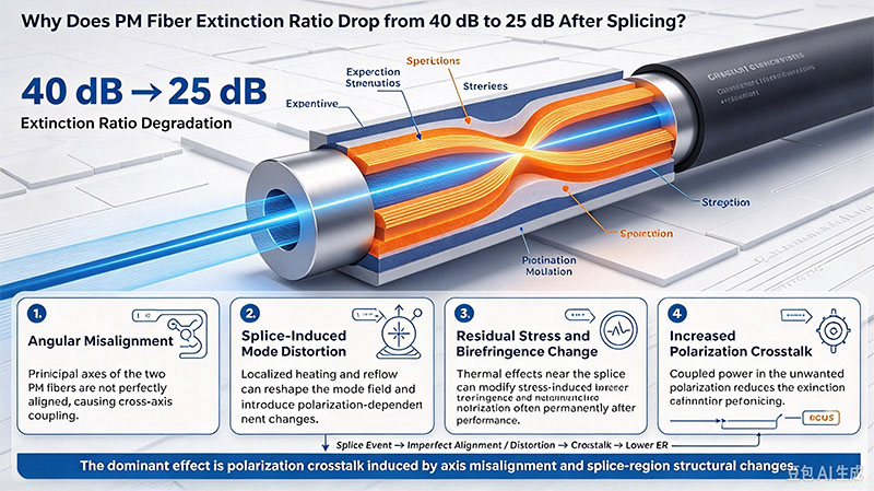
Why Does PM Fiber Extinction Ratio Drop from 40 dB to 25 dB After Splicing?
A polarization-maintaining (PM) fiber delivers an extinction ratio (ER) of 40 dB before splicing. After splicing, the value drops to just 25 dB. You adjust the fusion splicer, try different discharge settings, and still cannot recover the original performance.
The problem may not be the splicer settings alone.
For PM fibers, splice quality is not determined solely by insertion loss or core alignment. The integrity of the fiber's polarization-maintaining structure, angular alignment, and thermal history can also affect the extinction ratio. Understanding these factors is essential when splicing PANDA or other PM fibers for interferometers, coherent optical systems, fiber-optic gyroscopes, and precision sensing applications.
1. What Does Extinction Ratio Mean in PM Fiber?
A PM fiber is designed to maintain the polarization state of light by supporting two orthogonal polarization modes with different propagation constants.
The extinction ratio is commonly used to characterize the relative optical power associated with the principal polarization axes. In a simplified representation,
[
ER=10\log_{10}\left(\frac{P_{\mathrm{major}}}{P_{\mathrm{minor}}}\right)
]
where (P_{\mathrm{major}}) and (P_{\mathrm{minor}}) represent the optical powers measured along the dominant and orthogonal polarization axes under the specified measurement conditions.
A higher ER generally indicates better polarization discrimination.
Consider the following example:
Before splicing: An ER of 40 dB corresponds to a power ratio of 10,000:1.
After splicing: An ER of 25 dB corresponds to a power ratio of approximately 316:1.
A 15 dB reduction therefore represents a substantial deterioration in the measured polarization extinction.
However, ER is a measurement-dependent quantity. The result can also depend on how the fiber axes are aligned, the launch polarization, the measurement method, and the measurement setup. Before concluding that a splice has degraded the fiber, make sure that the measurements before and after splicing were performed under comparable conditions.
2. Why Can Splicing Degrade the Extinction Ratio?
2.1 Polarization coupling between the principal axes
PM fibers use built-in birefringence to help preserve the polarization state of transmitted light. In PANDA fibers, for example, stress-applying elements create the stress distribution responsible for this birefringence.
A splice introduces a localized transition between two fiber sections. If their polarization axes are misaligned, or if the splice changes the local stress distribution, optical power can couple between the two principal polarization modes.
This coupling can reduce the measured ER even when the splice has very low insertion loss.
That distinction is important: low splice loss does not necessarily mean good polarization extinction. A splice can transmit nearly all the optical power while still degrading polarization performance.
The actual degradation depends on factors such as angular misalignment, the fiber design, the splice geometry, the thermal process, and the measurement conditions. A splice should therefore be evaluated using both insertion loss and polarization-related measurements when the application requires high ER.
2.2 Three potential contributors to ER degradation
Cause 1: Fiber-end angle and axis misalignment
The condition of the fiber end face matters because the geometry of the prepared fiber and the alignment of the principal axes influence the splice.
An angled or poorly prepared end face can complicate alignment and create an imperfect transition between the two fiber sections. More importantly, angular misalignment between the PM fiber axes can cause polarization coupling.
Do not confuse these two issues: the physical end-face angle and the relative orientation of the fiber's slow and fast axes are different parameters. Both may need to be checked.
Recommended checks:
Inspect end-face quality and geometry before splicing.
Verify that the splicer supports the relevant PM fiber type and alignment procedure.
Confirm that the principal polarization axes are correctly aligned.
Check whether the measured ER changes when the splice is rotated or when the measurement launch conditions are repeated.
The original source suggests an end-face angle below 0.3° as a target in its example. This should be treated as a process-specific recommendation rather than a universal acceptance limit; the applicable specification depends on the fiber, preparation method, and equipment.
Cause 2: Lateral misalignment in the splice region
A PM fiber's polarization-maintaining structure is not defined by its core alone. In a PANDA fiber, the relative positions of the core and stress-applying elements determine the stress distribution and birefringent behavior.
Consequently, a splice with acceptable core alignment may still have unsatisfactory polarization performance if the fiber structures or principal axes are not properly aligned.
This is one reason why conventional splice-loss optimization may not be sufficient for demanding PM applications.
Recommended checks:
Confirm that the splicer is configured for the correct PM fiber design.
Inspect the alignment procedure and available axis-detection functions.
Verify that the two fiber sections have compatible axis orientations.
Compare ER before and after splicing rather than relying on estimated splice loss alone.
The original source gives examples of ER degradation associated with lateral offsets of 1–2 μm. These values should not be treated as universal conversion factors: the actual effect depends on fiber geometry, the type of misalignment, and the measurement method.
Cause 3: Thermal disturbance of the stress structure
Fusion splicing uses a high-temperature discharge to soften and join the glass. The heat can affect the local stress distribution around the splice, including the region associated with the stress-applying elements in a PANDA fiber.
Because the birefringence of a PM fiber is related to its internal stress distribution, a change in that distribution can alter the local polarization behavior.
This does not mean that every high-temperature splice will cause a large ER loss. The result depends on the discharge profile, heating duration, fiber structure, and splicing process.
Recommended checks:
Use a qualified PM-fiber splicing program as the starting point.
Evaluate discharge power and duration systematically.
Avoid assuming that a longer or stronger discharge will improve polarization performance.
Measure both splice loss and ER when comparing process settings.
Check the fiber manufacturer's recommendations for the specific fiber construction.
A low-power, short-duration process may reduce thermal disturbance in some cases, but it must still provide sufficient glass fusion and mechanical strength. The correct balance should be established experimentally.
3. Why Splicer Parameter Optimization May Not Solve the Problem
Fusion splicer settings primarily control the heating process and the alignment and joining of the fiber ends. They cannot automatically correct every issue associated with end-face preparation, fiber-axis orientation, or changes in the local stress structure.
Consider a typical troubleshooting scenario:
A splice has low insertion loss and the splicer reports good alignment, yet the measured ER drops from 40 dB to approximately 27 dB.
Continuing to adjust discharge power without investigating other variables may produce little improvement.
A more effective approach is to separate the problem into three categories:
Geometric factors: End-face condition, angular alignment, fiber-axis orientation, and lateral offset.
Thermal factors: Discharge power, heating duration, and the effect of the fusion process on the local stress structure.
Measurement factors: Launch polarization, axis alignment at the measurement interface, connector condition, and repeatability of the ER measurement.
This approach helps determine whether the dominant limitation comes from the splice itself, the preparation process, or the measurement setup.
4. A Practical Troubleshooting Workflow
When ER falls significantly after PM fiber splicing, follow a controlled diagnostic sequence.
Step 1: Verify the measurement
Measure ER before and after splicing using the same method and comparable launch conditions. Confirm the measurement instrument's calibration, fiber-axis orientation, and connection repeatability.
Step 2: Inspect fiber preparation
Check cleave quality, end-face geometry, cleanliness, and any visible damage. Do not assume that an acceptable visual inspection alone proves the end face meets the required geometric specification.
Step 3: Verify polarization-axis alignment
Confirm that the splicer is configured for the correct PM fiber type and that the principal axes are aligned as intended. Where available, use the equipment's dedicated PM alignment and inspection functions.
Step 4: Review the fusion process
Start with the fiber manufacturer's recommended PM splicing program. Change one parameter at a time, such as discharge power or duration, and record the resulting splice loss and ER.
Step 5: Compare multiple samples
Repeat the procedure across several splices. Record ER before and after splicing, insertion loss, fiber type, preparation conditions, splicer settings, and measurement conditions.
A consistent ER reduction across multiple samples may indicate a systematic process or compatibility issue. Large variation between samples may point toward inconsistent preparation, alignment, or measurement conditions.
Step 6: Establish application-specific acceptance criteria
Do not use insertion loss as the only pass/fail criterion for a PM fiber splice. Define separate acceptance limits for insertion loss and ER based on the system requirements and the applicable fiber or component specifications.
5. Key Takeaways
A drop in PM fiber extinction ratio from 40 dB to 25 dB is significant, but it should not automatically be attributed to the fusion splicer.
The main factors to investigate are:
Fiber-end preparation and geometry.
Relative alignment of the principal polarization axes.
Lateral alignment and compatibility of the fiber structures.
Thermal effects introduced during fusion.
Repeatability and consistency of the ER measurement.
The practical lesson is straightforward: optimize the complete splicing process, not just the discharge settings.
For applications such as fiber-optic gyroscopes, interferometers, coherent optical systems, and precision fiber sensing, evaluate polarization performance alongside splice loss. A splice that looks excellent in terms of optical transmission may still fail to meet the application's ER requirement.
Engineering note: Numerical thresholds and examples should be validated against the specific PM fiber datasheet, splicer manufacturer's recommendations, and a documented test procedure before being used as production acceptance limits.